
Thermal-magnetic circuit breaker trip curves: how to choose them
The right thermal-magnetic circuit breaker trip curve ensures the safety and regulatory compliance of an electrical system, as it determines the reaction time of the device in the event of an overcurrent. Picking out the one with the curve best suited to the system’s needs from among the types of thermal-magnetic circuit breakers available prevents unwanted tripping and helps ensure continuity of service and prevent financial losses.
Why trip curves are fundamental in electrical protection
The thermal-magnetic circuit breaker incorporates two release mechanisms that work in synergy. The thermal release unit, based on a bimetallic strip that flexes proportionally with the passage of current, intervenes when the circuit is subjected to prolonged overload, i.e. a current higher than that of normal load use. The magnetic trip unit, consisting of a coil, intervenes instantly in the event of high-intensity spikes of current, similar to a short circuit.
If you select a curve with a threshold that is too sensitive, the device will trip frequently during normal start-up, compromising operational continuity. A curve that is too permissive may not react promptly, leaving cables exposed to the risk of overheating and the potential risk of fire. For this reason, thermal-magnetic circuit breakers are developed to cover the full range of tolerance requirements in residential, commercial and industrial settings, such as those of the GEWISS 90 MCB Series.
How to read the characteristic curve of the thermal-magnetic circuit breaker
The characteristic curve of a thermal-magnetic circuit breaker is represented on a Cartesian graph that shows the trend of the trip time as a function of the fault current.
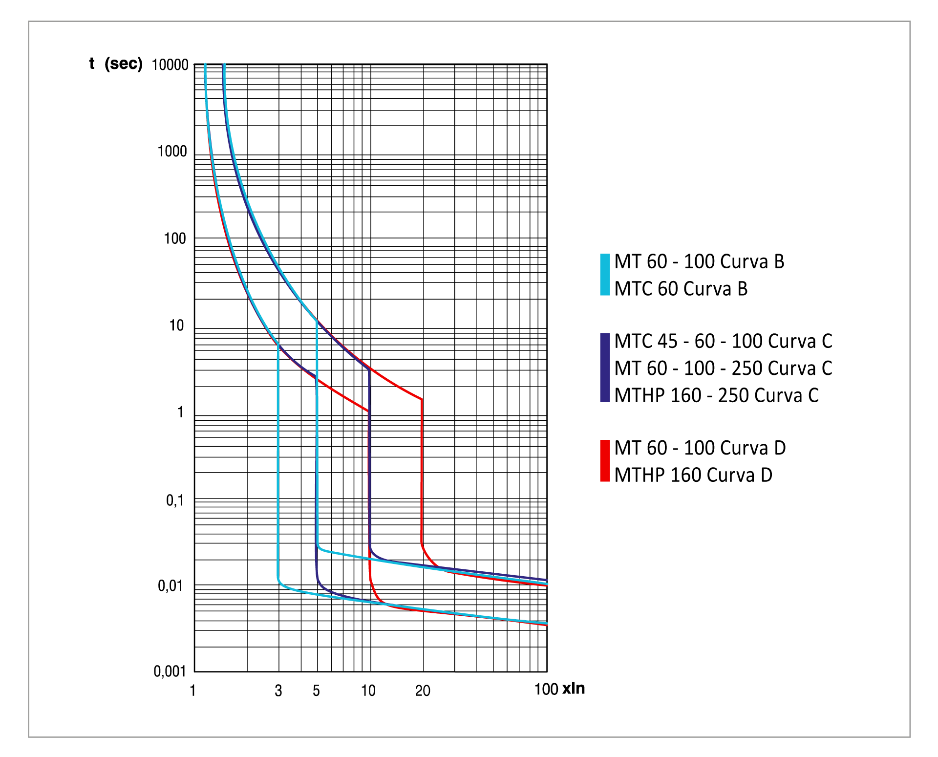
The horizontal axis (X) expresses the multiple of the rated current (In). For example, a value of 5x In indicates a fault current of five times the device’s rated current. The vertical axis (Y) represents the trip time, usually expressed in seconds.
The curve has two distinct zones. A slowly decreasing upper part, inversely proportional to the current, managed by thermal overload protection, and a lower part with a vertical drop, managed by magnetic short-circuit protection.
Classification of the thermal-magnetic circuit breaker trip curves
Thermal-magnetic circuit breaker B-curve
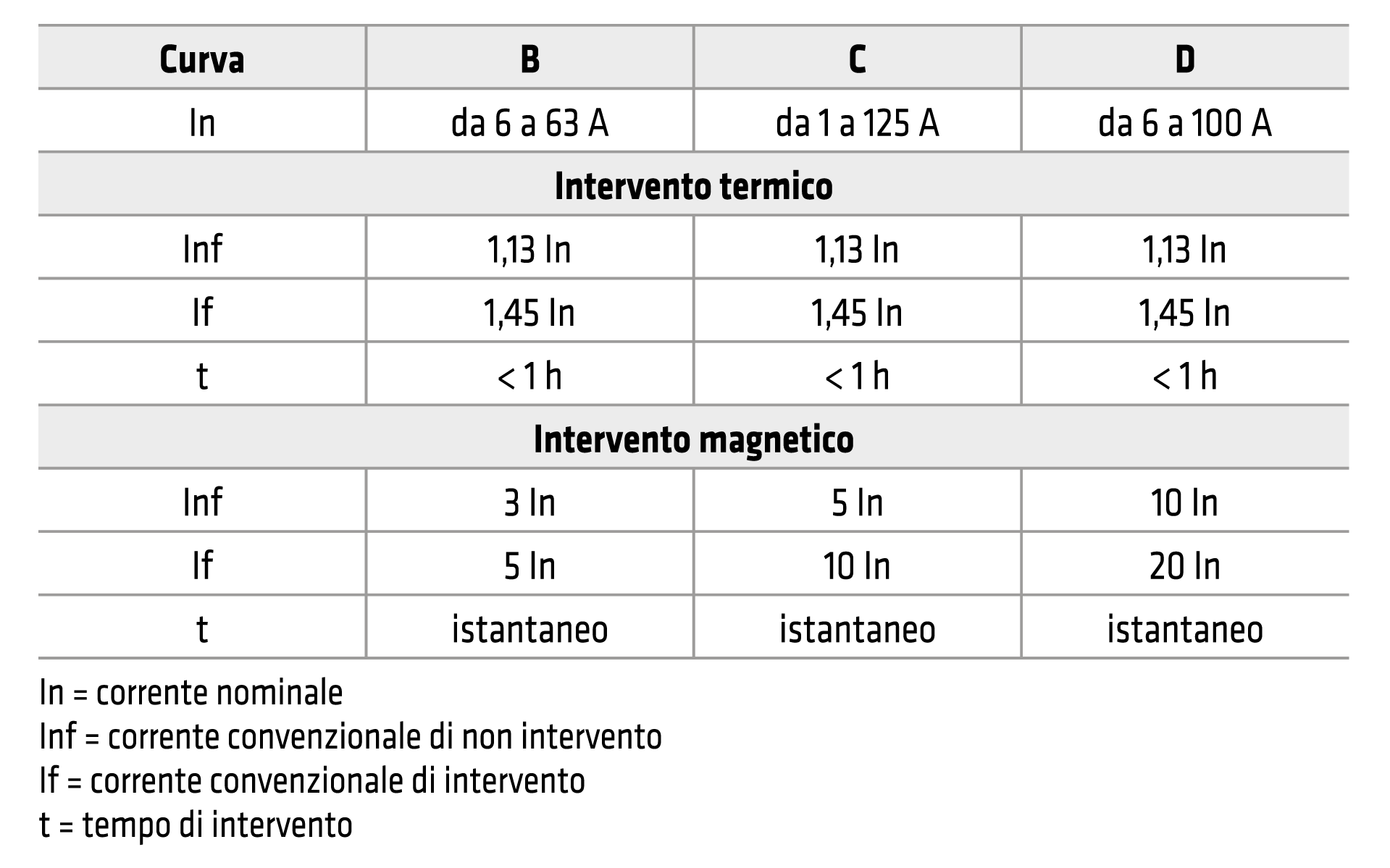
The thermal-magnetic circuit breaker B-curve trips when the magnetic trip threshold exceeds 3 to 5 times the rated value. This low threshold is ideal for protecting sensitive electronic devices, public lighting circuits, domestic and commercial applications, as the high impedance attenuates the short-circuit current.
Thermal-magnetic circuit breaker C-curve
The thermal-magnetic circuit breaker C-curve is the standard for most electrical applications, and tripping is triggered when the fault current is between 5 and 10 times the rated current. The C-curve provides a balance between fault sensitivity and tolerance to moderate start-up current spikes. It is widely used in residential consumer units for sockets and small appliances, and in industrial settings for HVAC systems, mixed resistance-inductance loads, and low-power motors.
Thermal-magnetic circuit breaker D-curve
The D-curve thermal-magnetic circuit breaker is designed to withstand very high transient overcurrents: the magnetic trip unit only trips when the current exceeds 10 to 20 times the rated value. It is used in industrial plants for starting high-power motors, transformers and industrial welders, thanks to a delay in the circuit opening that allows the machine inrush current to dissipate in complete safely.
From plant protection to operational continuity
In manufacturing environments, the choice between different types of residual current devices, thermal-magnetic circuit breakers and their respective curves directly influences productivity. For example, choosing between a C- or D-curve thermal-magnetic circuit breaker allows you to reconcile conductor protection with the peak currents generated by the loads.
To increase operational continuity and reduce economic damage, the enclosure architecture often includes switch-disconnectors to isolate just the damaged sections of the circuit, or those undergoing maintenance, to ensure operator safety. Together with these, the use of automatic reset systems allows power to be restored after a trip caused by transient network disturbances (such as lightning), performing a preventive insulation check to rule out the presence of permanent faults.
FAQ
The choice is made by analysing the downstream loads. If the system supplies electronics or long lines, the B-curve is the best option; for standard utilities and mixed residential loads, the C-curve is used; for industrial machinery with high inrush peaks, the D-curve is required.
The circuit breaker B-curve has a low magnetic threshold (3-5 times In), making it more suitable for electronics. The circuit breaker C-curve tolerates higher peaks (5-10 times In) and is the standard and versatile solution for most residential and commercial utilities.
A thermal-magnetic circuit breaker D-curve is used in the presence of highly inductive loads requiring high inrush currents at start-up, such as large transformers, industrial motors or welders. Its tolerance prevents the inrush current from causing a nuisance trip.
Explore the related Series

Trending Topics
Related articles


Show other categories


You can enter the Gewiss world by consulting the sites available for each country, differentiated by language, services, and catalogue offerings
Choose your country


Check your country
You are browsing the International site but it seems that you are in {{country}}. Do you want to update your country?

Yes, go to the website for {{country}}

No, stay on the International site