PBT-Q
Low-voltage systems and boards software for design and estimation

PBT-Q allows you to design and estimate the electrical low-voltage installation system in a simple and quick way.
Main functions offered by the software (this tool):
- Drawing of the electrical scheme
- Calculation of the parameters of the electrical system
- Automatic or manual configuration of the structure
- Thermic verification
- Auxiliary circuits drawing
- Measure circuits drawing
- Estimation of the system
Information
Details
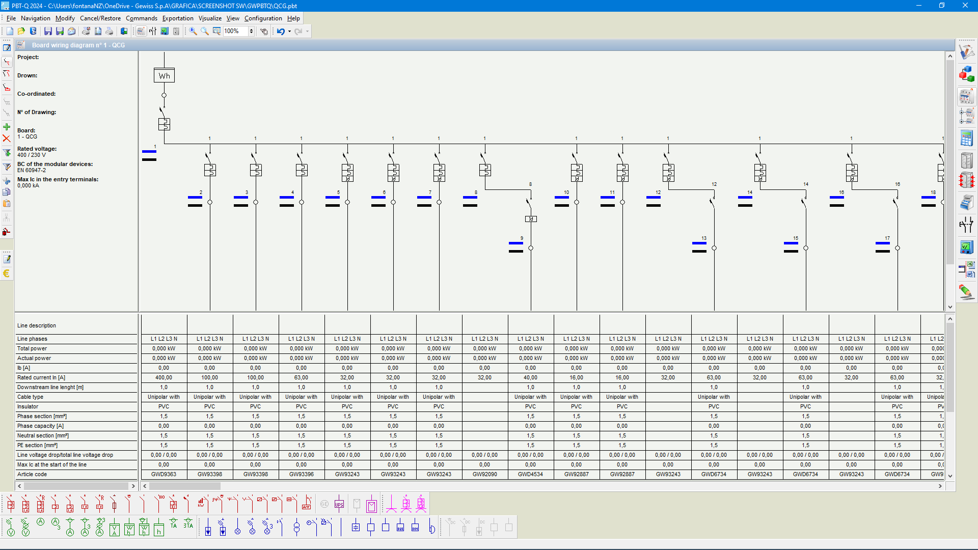
Drawing of the scheme
The drawing mode of the single-line circuit diagram is semi-automatic: once the component to be inserted into the diagram has been selected and the insertion mode defined (series, parallel, start of a new panel), the symbol is automatically positioned on the drawing sheet. PBT-Q also has an additional graphic drawing mode, which allows text, lines, and shapes with customisable characteristics to be inserted.
Calculation of the electrical system
Concluded with drawing of the single-line electrical scheme, the program does the calculation of the parameters of the electrical system and chooses the components:
- load current and short circuit;
- voltage drop;
- dimensioning of the wiring;
- selection of the manoeuvre and protection devices.
The information and the relative data of the installation system (type of distribution system, supply characteristics, etc.) and of the components (length and type of conductor, data of the loads, etc.), can be inserted and/or modified at any time (before or after the dimensioning). The electrical parameters of the devices are put automatically into the diagram, and the single headings can be personalised by the user.
It is possible to even “block” all or only the selected devices and/or wiring: during the check phase, the program signals possible anomalies (and suggests the replacement of the blocked components with more suitable ones).
The presence of photos of the devices (switches, measuring devices, signalling, commands, etc.) makes the selection much easier.
The devices can be accessorised, where available; the execution can also be selected (fixed, plug-in, withdrawable, etc.).
The program also has a series of functions and short-cuts that make planning quicker and more efficient (for example, the direct selection of the symbols from the message window, an operation that allows to modify, in an immediate way, all the data that the messages refers to).
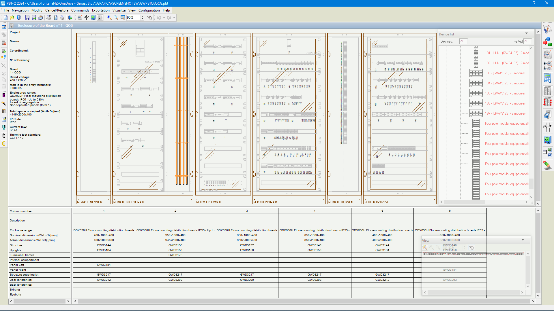
Configuration of the structure
After creating the single-line electrical scheme and dimensioning the manoeuvre and protection devices, it is possible to configure the structure in an automatic or manual way.
Automatic board configuration: through one click, PBT-Q selects a complete board, immediately drawn (and priced), that can be modified by the user; during the modifications, the enclosure is updated in real time (drawing and price).
Manual board configuration: the program offers all the compatible enclosures with the devices present in the circuit and allows, in a simple way, the creation of the board, showing (while making the board) both the shape of the devices to be inserted (highlighting those already inserted) and the structure of the scheme (also highlighting here the components already inserted). To complete the board, it is possible to also select the busbar distribution system among those compatible with the enclosures used.
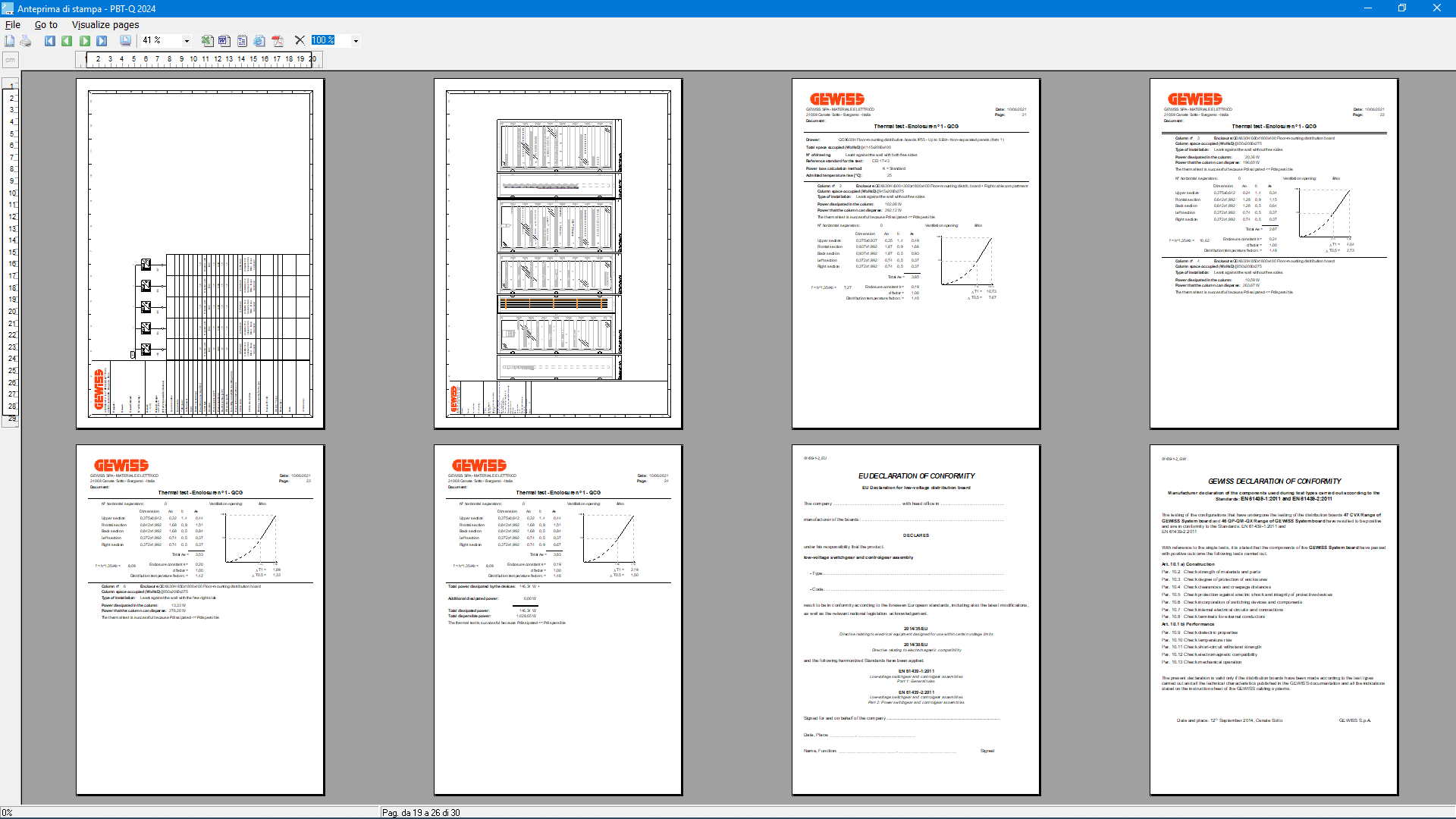
The program then carries out the thermic verification, as prescribed by the electrical enclosure standard, according to various methods selected by the user.
Quick estimation
The program allows to carry out a quick estimation by selecting all the devices to be inserted through proper filters (data, description, or directly from the code) or by the direct importing of the material list from other software (Word, Excel, Text, etc.).
Auxiliary and measure circuits drawing
By PBT-Q, you can draw auxiliary and measure circuits, using a complete symbols library. To create a diagram, it’s possible to insert symbols freely or to use the elements of the devices inserted into the electrical diagram (coils, contacts, instruments, etc.). All the operations are very simple, aided and facilitated by automatisms (automatic symbol denominating, colouring and assembling, easy drawing of the connections that accommodate themselves to the symbols movement).
Documentation
Project documentation (schemes, front of the board, installation/board/device data, conformity declarations, list of materials) is personalisable (for example, company logo) and exportable in various formats (xls, rtf, pdf, txt, html and dxf).
Screenshot


